Compendium: A loose compilation of helpful information of a subject.
Instructions Video:
https://youtu.be/RQIizXtf9oo
Optiboot Bootloader:
https://github.com/Optiboot/optiboot
Firmware Settings:
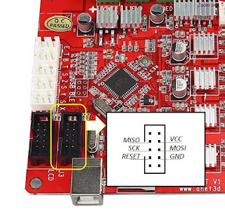
Bootloader brennen geht nicht
avrdude: Version 6.3-20190619
Copyright
(c) 2000-2005 Brian Dean, http://www.bdmicro.com/
Copyright
(c) 2007-2014 Joerg Wunsch
System wide
configuration file is
"C:\Users\maboo\AppData\Local\Arduino15\packages\MightyCore\hardware\avr\2.0.5/avrdude.conf"
Using Port
: COM8
Using
Programmer : stk500v1
Overriding
Baud Rate : 19200
AVR Part
: ATmega1284P
Chip Erase
delay : 55000 us
PAGEL
: PD7
BS2
: PA0
RESET
disposition : dedicated
RETRY pulse
: SCK
serial
program mode : yes
parallel
program mode : yes
Timeout
: 200
StabDelay
: 100
CmdexeDelay
: 25
SyncLoops
: 32
ByteDelay
: 0
PollIndex
: 3
PollValue
: 0x53
Memory
Detail :
Block Poll Page
Polled
Memory
Type Mode Delay Size Indx Paged Size Size #Pages MinW MaxW
ReadBack
----------- ---- ----- ----- ---- ------ ------ ---- ------ -----
----- ---------
eeprom
65 10 128 0 no 4096 8 0 9000 9000 0xff
0xff
flash
65 10 256 0 yes 131072 256 512 4500 4500 0xff
0xff
lock
0 0 0 0 no 1 0 0 9000 9000 0x00
0x00
lfuse
0 0 0 0 no 1 0 0 9000 9000 0x00
0x00
hfuse
0 0 0 0 no 1 0 0 9000 9000 0x00
0x00
efuse
0 0 0 0 no 1 0 0 9000 9000 0x00
0x00
signature
0 0 0 0 no 3 0 0 0 0 0x00
0x00
calibration 0 0 0 0 no 1 0 0 0
0 0x00 0x00
Programmer
Type : STK500
Description
: Atmel STK500 Version 1.x firmware
Hardware
Version: 2
Firmware
Version: 1.18
Topcard
: Unknown
Vtarget
: 0.0 V
Varef
: 0.0 V
Oscillator
: Off
SCK period
: 0.1 us
avrdude: AVR device
initialized and ready to accept instructions
Reading |
################################################## | 100% 0.02s
avrdude: Device
signature = 0x000000 (retrying)
Reading |
################################################## | 100% 0.02s
avrdude: Device
signature = 0x000000 (retrying)
Fehler beim Brennen
des Bootloaders.
Reading |
################################################## | 100% 0.02s
avrdude: Device
signature = 0x000000
avrdude: Yikes!
Invalid device signature.
Double
check connections and try again, or use -F to override
this check.
avrdude done. Thank
you.
- Board ausbauen
- Wird an USB nicht erkannt
- 9V externe Spannung anlegen
Bootloader brennen geht immer noch nicht aber neue Fehlermeldung.
Reset kurz beim Bootloader brennen:
Geht!
Bootloader wurde gebrannt!
Kein Extra Kondensator zwischen GND und Vcc war nötig.
Nun zur Firmware
Wichtige Videos und Links:
Upgrade an Ender 3 with Marlin 2.0 and BLTouch:
https://www.danbp.org/p/en/node/142
Unbrick Anet A8 Mainboard (via USBISP)
https://www.youtube.com/watch?v=hCGF-UdPSOA
Skynet AVRDUDE Programm:
ANET A8 Board - fix dead stepper with external stepper driver
http://lokspace.eu/how-to-fix-failed-stepper-driver-on-the-anet-v1-0-board-and-use-external-reprap-stepper-driver/
There are only 3 signals that drive each driver – X_DIR – sets the direction in which the stepper rotates, X_STEP – sending a pulse here makes the motor execute a “step”, and ENABLE – enables/disables the stepper.
Apart from these, I also needed power – VCC (5V – power for the logic), VMOT (12V – power for the motor) and GND.
Apart from these, I also needed power – VCC (5V – power for the logic), VMOT (12V – power for the motor) and GND.
I was able to trace the first 3 to the following points on the mainboard:
- X_DIR – test point T13 (pin 24 on the atmega1284p)
- X_STEP – test point T13 (pin16)
- ENABLE – test point T19 (pin15)
Getting the rest was easy – I got the 5V from the output pin of the 5V regulator, and 12V from the input pin. And GND is shown on the picture below.
The ENABLE signal wire can be soldered on alternative location – on one of the pins of R8 (shown on the picture below). It’s better there, because the test points are too small and you can ruin them easily. Unfortunately X_DIR and X_STEP use direct connection between the atmega and the driver so there are no alternative points where you can solder the wires.
The ENABLE signal wire can be soldered on alternative location – on one of the pins of R8 (shown on the picture below). It’s better there, because the test points are too small and you can ruin them easily. Unfortunately X_DIR and X_STEP use direct connection between the atmega and the driver so there are no alternative points where you can solder the wires.
After several trials, the board seems to be bricked. In addition to the problem with the very small memory, I decided to turn away from using the original Melzi board and look for a board with enough memory to install a full Marlin.


